.AudiaFUSION Networked Amplified Processor is an 8-channel modular amplifier with CobraNet digital I/O, digital signal processing, and automatic channel or device failover. The device provides amplified outputs to directly drive 4, 6, or 8 Ohm low-impedance loudspeaker systems or 70 or 100V constant voltage loudspeaker systems. When placed into the layout from the Object toolbar, AudiaFUSION output blocks are software configurable for 100–600 watts per channel. The combined wattage of all power amplifier modules in an AudiaFUSION chassis can be up to 2400 watts.
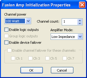
An AudiaFUSION unit appears in Audia software as an output block. When an AudiaFUSION device is chosen from the I/O menu in the Object toolbar and the mouse is clicked in the layout window, an AudiaFUSION Amp Initialization Dialog window appears.
Channel Power is used to select the power rating (in watts) for all channels controlled by that block.
Channel Count is used to select the number of amplifier channels that block will provide. The maximum number of channels available with this parameter is affected by the Channel power setting. For example, a setting of 600 watts would result in a maximum Channel count of 4, as 600 watts x 4 channels = 2400 watts, which is the maximum amplifier capacity of one AudiaFUSION frame.
Enable Logic Outputs is used to determine if the AudiaFUSION block will provide logic output connection points.
Group Logic Outputs is used when Enable logic outputs is checked to determine what complement of logic outputs are provided on the AudiaFUSION block. If Group logic outputs is unchecked, the block will feature six logic outputs per channel, plus a global Fan Stuck Rotor output. The six logic outputs for each channel correspond to the six fault types that an AudiaFUSION amplifier channel can report: Heat Sink, Short Circuit, Channel Failure, Excessive Clipping, Low Impedance, and High Impedance.
If Group Logic Outputs is checked, only two logic outputs are provided per amplifier channel, Alarm and Warning, plus the global Fan Stuck Rotor. In this mode, the Alarm output is a logical OR of the Heat Sink, Short Circuit, and Channel Failure Alarms. The Warning output is a logical OR of the Heat Sink, Excessive Clipping, Low Impedance, and High Impedance Warnings. If an AudiaFUSION block is initialized with Device Failover active, two additional global logic outputs are provided, Primary Device Good and Secondary Device Good.
Amplifier Mode is used to specify whether the amplifier channels controlled by that block will be configured as Low Impedance – for standard 4, 6, or 8 Ohm loudspeakers – or 70V or 100V Constant Voltage – for connection to distributed, transformer-coupled loudspeakers.
Enable Device Failover is used to establish an automatic device failover mode using two identically configured AudiaFUSION units. The two units become a logical pair and are referred to as the Primary Device and Secondary Device. If the Primary Device experiences an alarm, it will automatically transfer control to the Secondary Device, which will continue to process and distribute audio, taking on all of the functions of the Primary Device.
When device failover occurs, switching relays on the AM600 amplifier modules will physically break loudspeaker connections on the Primary Device and make connections on the Secondary Device. As a result, it is necessary to have two physical cable runs to each loudspeaker connection, one from the Primary Device and one from the corresponding output channel on the Secondary Device, or have a jumper between the primary device card and the secondary device card in order for audio to continue to flow when device failover occurs. Another possible method for device failover is to have independent speaker runs for both the primary and secondary devices.
When an AudiaFUSION block is created with Enable Device Failover checked, it will appear in the layout window as two devices “fused” together. The properties and attributes of the Secondary Device cannot be edited or modified independently of the Primary Device. The two units are always configured identically.
When a layout is compiled that includes an AudiaFUSION block with device failover enabled, the Secondary Device will receive a device ID that is different from the Primary Device; however, during a failover, any received ATP command strings intended for the Primary Device are automatically routed to the Secondary Device, and any acknowledgement messages that the Secondary Device returns will contain the device ID of the Primary Device, even though the Primary Device is no longer the active unit. This preserves third-party control support during device failover.
A device failover pair will appear in the Equipment Table with device types that are read-only. If either the Primary or Secondary Device is removed from the Equipment Table, the partner unit will also be removed.
Enable Channel Failover for these Channels provides a means of establishing an automatic channel failover mode using two adjacent channels within a single AudiaFUSION unit. The two designated channels become a logical pair and are referred to as Primary Channel and Secondary Channel. If the Primary Channel experiences a channel alarm, it will automatically transfer control to the Secondary Channel, which will continue to process and distribute audio, taking on all of the functions of the Primary Channel.
When channel failover occurs, switching relays on the AM600 amplifier modules will physically break loudspeaker connections on the Primary Channel and make connections on the Secondary Channel. As a result, it is necessary to have two physical cable runs to each loudspeaker connection, one from the Primary Channel and one from the Secondary Channel, in order for audio to continue to flow when channel failover occurs.
When failover occurs, any received ATP command strings intended for the Primary Channel are automatically routed to the Secondary Channel, and any acknowledgement messages that the Secondary Channel returns will contain the index value of the Primary Channel, even though the Primary Channel is no longer the active channel. This preserves third-party control support during channel failover.
Note: Channel failover is not available when Device failover is being used, and vice versa.
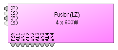
The AudiaFUSION block provides connection points for audio coming into the block, and logic output connection points for fault indications.
If channel failover is in use, the Primary Channel will be indicated with (P) and the Secondary Channel with (S). The connection point for the Secondary Channel will appear in a light gray color and will not accept a wire connection. Instead, the audio signal connected to the Primary Channel will automatically be used as the input for the Secondary Channel when channel failover occurs.
If device failover is in use, the block will appear as two AudiaFUSION blocks “fused” together. The Primary (left) side will have the audio and logic connection points and the Secondary (right) side will have no connection points.
The complement of logic output connection points that are available is dependent on whether the Group Logic Outputs property in the AudiaFUSION block initialization dialog window is checked or not. When that setting is unchecked, the block will feature six logic outputs per channel, plus a global Fan Stuck Rotor output. The six logic outputs for each channel correspond to the six fault types that an AudiaFUSION amplifier channel can report: Heat Sink, Short Circuit, Channel Failure, Excessive Clipping, Low Impedance, and High Impedance.
If Group Logic Outputs is checked, only two logic outputs are provided per amplifier channel, Alarm and Warning, plus the global Fan Stuck Rotor. In this mode, the Alarm output is a logical OR of the Heat Sink, Short Circuit, and Channel Failure Alarms. The Warning output is a logical OR of the Heat Sink, Excessive Clipping, Low Impedance, and High Impedance Warnings. When the AudiaFUSION block is initialized with Device Failover active, two additional global logic outputs are provided, Primary Device Good and Secondary Device Good.
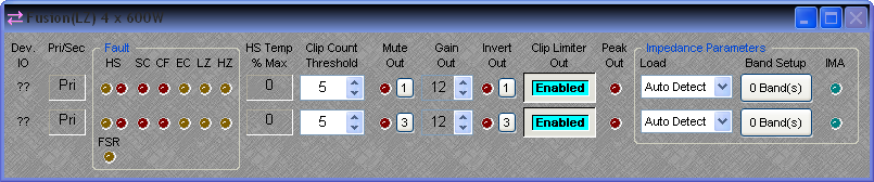
Device I/O indicates which hardware input is associated with that software channel. If Device failover or Channel failover is in use, an additional column to the right of the Device I/O field will indicate whether that device or channel is Primary (Pri) or Secondary (Sec).
There are two types of Faults that the AudiaFUSION can report, categorized as Warnings or Alarms, depending on their severity. A Warning indicates that some aspect of the system is not performing within normal specification. Audio is still passing, but if the condition causing the Warning is not corrected, failure may occur. An Alarm indicates that some aspect of the system has failed and audio is no longer passing on that channel. If Channel or Device Failover has been enabled for that channel or device, an Alarm will cause failover to occur, whereas a Warning will not.
List of AudiaFUSION Faults:
Heat Sink (HS) Warning indicates that the heat sink on the AM600 amplifier module has risen above 3 degrees Celsius below its maximum cooling capacity. The amplifier module will automatically attenuate audio by 3 dB to attempt to reduce the temperature of the heat sink. If the temperature continues to rise, the HS Warning will become an HS Alarm (see below). The heat sink temperature must fall below 6 degrees Celsius below its maximum cooling capacity to clear the HS Warning and restore full output level.
Heat Sink (HS) Alarm indicates that the heat sink on the AM600 amplifier module has reached its maximum cooling capacity and audio on that channel will be stopped. Failover will occur if enabled on that channel or device. If failover is not enabled, audio will only be restored on that channel when the heat sink temperature fall below 6 degrees Celsius below its maximum cooling capacity.
Short Circuit (SC) Alarm indicates that there may be a short circuit on the load on that channel. The output current of the amplifier module is continuously monitored. If the current exceeds the maximum rated current amount, or if the load impedance monitoring circuit calculates an effective load of 1 Ohm or less, the SC Alarm will occur and audio will be stopped on that channel. After a brief wait, the amplifier module will attempt to restart audio. If the condition that caused the SC Alarm persists, the amplifier module will continue to wait and try again. It will do this indefinitely, unless failover has been enabled on that channel or device, in which case the Short Circuit Delay attribute in the Property Sheet of the AudiaFUSION block will determine how long the amplifier module will retry before failover occurs.
Channel Failure (CF) Alarm indicates that a hardware failure of the amplifier module has occurred. Audio will be stopped on that channel and channel or device failover will occur, if enabled.
Excessive Clipping (EC) Warning indicates that amplifier output clipping has occurred (or would have occurred if the Clip Limiter had not been enabled) and is affected by the Clip Count Threshold parameter (see Clip Count Threshold below).
Low Impedance (LZ) Warning indicates that the impedance monitoring circuit (if enabled) has detected an impedance that is lower than the minimum allowed by the current setting of the Tolerance parameter (see Band Setup below).
High Impedance (HZ) Warning indicates that the impedance monitoring circuit (if enabled) has detected an impedance that is higher than the maximum allowed by the current setting of the Tolerance parameter (see Band Setup below).
HS Temp % Max indicates the temperature of the heat sink located on the amplifier module, given as a percentage of maximum cooling capacity. If the heat sink temperature rises to 92%, a Heat Sink (HS) Warning will occur and the amplifier module will attenuate its output by 3 dB to attempt to reduce the temperature of the heat sink. If the heat sink temperature rises to 100%, a Heat Sink (HS) Alarm will occur and audio on that channel will be stopped.
Clip Count Threshold is the number of consecutive 100 ms segments of audio containing at least one clipped sample that are needed to illuminate the Excessive Clipping (EC) Warning indicator. The Clip Count Threshold affects the response of the EC Warning indicator; if the Clip Count Threshold is set to 1, the Excessive Clipping (EC) Warning indicator becomes a “standard” or instantaneous clip indicator, rather than an “excessive” or long-term clip indicator.
Mute Out is used to mute the audio on that channel. Gain Out (dB) is used to set the amplifier sensitivity. This control ranges from 0 dB (unity gain) to 24 dB (default is 12 dB). Invert Out is used to reverse the polarity of the output signal. Clip Limiter Out is used to control whether the analog clip limiting circuit on the amplifier module is enabled or not. When enabled, this limiter attenuates any signal peaks that would otherwise cause the amplifier’s output to clip. Peak Out is a signal peak indicator that illuminates when the output signal is within 3 dB of clipping the amplifier.
Load is a setting that allows the user to select the intended speaker load (4, 6, or 8 Ohm) for all channels controlled by that block. Choosing Auto Detect will allow the AM600 amplifier module to automatically set the load impedance based upon the amplifier output current. This setting is only available if the Amplifier Mode has been designated as Low Impedance. (See Amplifier Mode above)
Band Setup produces a control dialog window that allows the Impedance Monitoring algorithm to be configured. The text on the button control will indicate the number of frequency bands that have been defined for impedance monitoring.
Impedance Monitoring Active (IMA) is an indicator that illuminates when impedance monitoring is active.
Frequency Band Setup is a dialog window that contains parameters for defining frequency bands over which impedance monitoring should occur. Up to four bands can be defined. Active Band is used to choose which band’s parameters are displayed for modification. Center Freq (Hz) is the center frequency of the active band. Bandwidth (Hz) is the bandwidth of the active band. Tolerance % defines the amount above or below the baseline impedance curve that, when exceeded, causes a High Impedance or Low Impedance Warning to occur. Setting Tolerance % to a lower number means that a smaller change in the load impedance curve will be sufficient to cause a High Impedance or Low Impedance Warning. Setting Tolerance % to a higher number means that a larger change in the load impedance curve will be required to cause a High Impedance or Low Impedance Warning.
Add Band is used to add an additional band to the monitoring algorithm. Up to four bands can be defined. Remove Band will delete the highest-numbered band. Disable Alarms is used to bypass the impedance monitoring algorithm and suppress any High Impedance or Low Impedance faults that may be detected. Averaging length (samples) defines the number of impedance measurements that are collected and averaged to determine the load impedance curve. Setting this value to a lower number will allow the curve to be drawn and updated more quickly, at the expense of some accuracy or “curve jitter.” Setting this value to a higher number will cause the curve to be drawn and updated more slowly, but with smoother and more accurate data.
Capture Alarm Baseline Data is used to populate the Alarm Baseline Data fields with the currently displayed Realtime Impedance Data. The Realtime Impedance Data is obtained by dynamically measuring load voltage versus current at several different frequencies throughout the audible spectrum. The results of this impedance calculation are affected by the amplitude and spectral characteristics of the signal passing through the amplifier module. For best results, a wideband signal such as pink noise should be played at a sufficient level to overcome the noise floor of the detection circuitry.
Impedance Monitoring Active is an indicator that illuminates when sufficient data has been entered for the impedance monitoring algorithm to begin monitoring that band.